Introduction
This article addresses the issue of modelling a local multi-carrier energy network. This problem can be considered as an extension of modelling a low voltage distribution network located at some urban or rural geographic area. But instead of use external power-flow analysis package to do the power flow calculations, as used in electric networks, in this work we integrate a multi-agent algorithm to perform the task, in a concurrent way to the other simulation tasks, and not only for the electric fluid but also for a number of additional energy carriers. As the model is mainly focused in system operation, detailed generation and load models were not developed. Instead we used data from The Solar City project, created by The Load Research Group, from the De Montefort University, Leicester.
Multi-carrier energy networks have high relevance as models of many complex physical systems. Because they appear anywhere in nature, they can serve as tractable instances of Complex Infrastructure Systems. Existing research treats nodes as homogeneous and so we also apply the ontology for conversion points developed for Adaptable, Sustainable Infrastructure research. This ontology highlights the major processes of conversion: (i) extract (production conversion); (ii) transform (final consumption conversion); (iii) deliver (spatial conversion); and, (iv) store (temporal conversion). Each process is enabled by a technology which determines the maximum efficiency of the conversion, its by-products or waste, and its optimal operating conditions. Uniquely, each conversion point is operated by agents who influence its performance constrained by relevant rules and regulations.
The functional components of our quantitative multi-carrier energy network model implement the conversion points’ ontology. Whilst this revised multi-carrier energy network model extends existing electrical network models, it does not go as far as the conversion points’ ontology and vision intends, which is to embrace all utility systems, including transportation, water, telecommunications and waste. However, to create a multi-carrier energy network represents a step towards this vision.
Power grid evolution
The electricity grid has been in continuous evolution, from its beginning in the early nineteenth century until now and probably will do so in the future, affecting to its structure and also to its elements, many of which have been improved, and others new have been created. The grid structure has gone from an initially distributed configuration, with small hydroelectric power plants supplying nearby towns, especially for lighting, to a more centralized one by successively merging companies from the mid-twentieth century, in the golden age of regulation for more than 60 years, and today is in a process of change to go back to being decentralized.
The old electricity grid is a wired network i.e. an assembly of electricity conductors through which the power flow is going from suppliers or generators to consumers or loads. Its main components are: power generators, transmission lines, voltage transformers, distribution lines and electric power loads where the electrical energy is consumed by customers.
Modeling
The following sections are dedicated to show how to model energy networks and also to try to extend the models. First a short summary of classical electrical grid modelling, then a possible way to extend it to cover multi-carrier energy networks and eventually a try to extend it even more, to cover infrastructure systems, are presented.
Power flow analysis
The electrical network is represented as a directed, weighted graph G=(V,E), where V is the set vertices (or nodes) and E is the set of edges (or lines) in the network. Weights are usually be given by the so called admittance matrix Y=[yij] that is the Laplacian Matrix, or Kirchhoff Matrix of G.
Engineers use models of the electrical power grid to calculate voltages and currents anywhere in a circuit. If voltages (or intensity sources) at generators are given and voltages and intensities at loads are unknown, then a linear system of equations results and mesh (or nodal) analysis can be used to solve the problem, using standard linear algebra methods.
But in the most usual problem in electrical power systems engineering, the statement is different and it leads to a non-linear system of equations. In this case, the most common method used is power-flow analysis. A very short summary of the method, explained in detail in classical power system books1,2, follows.
There are three node types, slack (only one), control and load, each denoted by a symbol,
being two complex variables, voltage v and apparent power s, associated to each. Nodes are usually called buses. The Ohm law, s=vi, relates power, voltage and intensity.
Given the specification: v is known and s is unknown for slack bus, (v,p) are known and (?,q) are unknown for control buses, s is known and v is unknown for load buses, then a non-linear system of equations is posed, for which the so called power-flow iterative approach (based on the Gauss-Seidel method) is usually used to calculate the unknowns. The resulting useful formulae, for each i-th bus,
are applied, depending on if it is a load bus (only the first one) or control bus (the second one and then the first one). The slack bus power is calculated at the end of iterations as the amount of power at all the other buses.This method is specially well suited to be adapted to agent-based modelling, because calculations are iterative and local at each node, so it is very easy to do it, simply by representing nodes by agents.
Extending the electrical grid
As agent-based models of the electrical grid were already made by the authors, for microgrids3, the method proposed in this article is extending these models to also cover Energy Networks.
But electrical elements are not enough for this, a more sophisticated idea if node, able to accommodate multidimensional flows, is needing.
This conceptualization is interesting because it could be extended further, to Infrastructure Network models, simply by adding more lines (for communications, policies, regulations, water flows, transport flows, etc.) and allowing hubs to implement conversion points8.
Energy networks
Electric?network?graphs
A multi-carrier energy network consist of a number of energy conductors, through which different kind of energy flows between the network nodes, usually using special fluids called energy carriers, where they can interact with each other and the environment. The idea to model these kind of networks is to exploit as much as possible the elements of electrical networks, trying to use them for other energy carriers and then combine them in a multi-carrier network (see Figure 1). For doing so, a re-thinking of the node and edge concepts, to extend them to the multi-carrier case is needed. For this, the Hub concept developed in 4, with some modifications is used, and also a special version of the multi-agent phpower-flow algorithm, developed by the authors5,6, has been developed. Previously calculated formulae are valid not only for electrical systems, but also for any other kind of energy carriers.
Energy kinds
The electric power it is not the only possible energy carrier, also gas and heat utilities are very useful to cover domestic energy demand. In the gas utility, a gas is flowing through pipes from some generator nodes where the fluid is pushed into the network to other consumer nodes where the chemical energy in the gas is transformed into heat for use it. In the heat utility, usually water (sometimes as steam) is flowing through the pipes from generators to consumers, where the thermo-dynamical energy in the gas is transformed to heat and used.
Table?1
Energy kinds
Another way to deliver energy that can be seen in books are old systems of mechanical power transmission, widely used during the Industrial Revolution, which, although not widely used today as heating services, are often used as subsystems within other facilities. These single mechanic systems do not use fluids nor pipes but energy goes directly from generator nodes to consumer nodes through a system of shafts and pulleys.
These are probably the four kinds of energy most used in existing facilities. There are, of course, other kind of possible energy transmission, such as electromagnetic energy through air or special media, light energy (sun, laser), etc., but in this paper, we will use only those four.
Moreover, although it is not really an energy transmission in the usual sense, a further kind of energy, communication, has been added. It represents digital signals that flowing through some media serve to send messages - usually related to events- between the network nodes, and it is responsible to the event driven digital changes in the network.
In this way, five energy kinds will be considered, as Table 1 summarizes. This gives the network a layered structure, thinking each energy kind flows in a different layer, which is not far from reality.
Energy Hubs
Electrical?socket?in?a?hub
An energy hub is a unit that provides the basic features of input and output, conversion, and storage for multiple energy carriers and represents a generalization or extension of the network node in an electrical system4. Each energy carrier introduces energy of a given type in the hub, where it can be transformed into energy of another type, but it can be also used and stored.
One can imagine five sockets into each hub to be used by the internal agents for communication, mechanical energy, electrical energy, chemical energy and thermal energy, respectively.
Suppose for example that a flow pe of electric energy comes through the electrical socket into the hub, where a part pem is converted into mechanical energy, a part pee is consumed, a part peg is converted into chemical energy, a part peh is converted into thermal energy, and the remaining power pes is stored.
After the respective conversion cem, cee, ceg, ceh, ces and efficiency ?em, ?ee, ?eg, ?eh, ?es, processes, the flows of mechanical lem, chemical leg and thermal leh energies are given to their respective connected loads and the remainder is stored as electric energy ee.
Also may be that the flows lme, lge, lhe are fed form the mechanical, chemical and thermal conversion processes, giving an amount lee+lme+lge+lhe of electric power flow, part of which, after the conversion res and efficiency ?es processes, is stored as electric energy ee, as Figure 2 shows.
From energy point of view only the four last of them are operative, so the energy conversion process at each hub can be represented as a block with four inputs pm, pe, pg, ph for input power flows, and four outputs lm, le, lg and lef or output load flows. The relationships between them are given by
or in matrix notation
L=EP
where P is the input power flow vector, L is the output load flow vector and E is the hub efficiency matrix.
Hub?internal?diagram
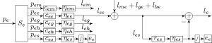
The complete block diagram of a hub, for four energy carriers, including energy stores, is shown in Figure 3 results.
Multi-carrier?energy?hub
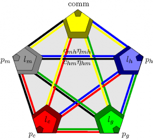
A much more simple and intuitive representation can be done using a graph like picture as the one that Figure 4 shows, where the dark zones represent energy storage elements, one near the power input an the other near the load, the clear zones represent loads, and the colored lines represent the conversion factors and efficiencies. This diagram is close to a System Dynamics representation.
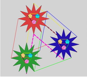
As this figure shows, there is a network inside each hub, so really each hub is a network, and therefore a multi-carrier energy network can be considered as a network of networks. Even more, each vertex of this is again a network.
Each of the small pentagons of Figure 5 corresponds to a hub like Figure 4 shows. And also that if we were to look very closely, we would see that each of the small pentagons at the vertices of the Figure 4 is actually a new hub, and so on, so definitely we have a recursive structure of network of networks.
This is not surprising at all since other complex networks such as the Internet and the Smart Grid7 have already been named that way
Multi-carrier?energy?network
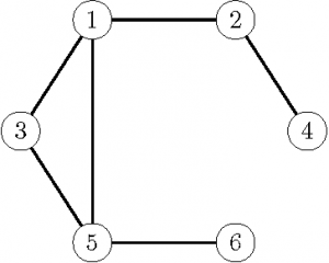
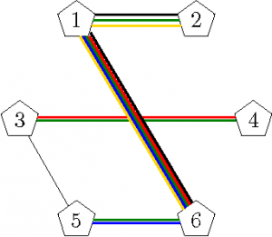
Figure 4 shows a possible multi-carrier energy network with six nodes where each of them is a multi-carrier energy hub. Note that each of the small pentagons of Figure 5 corresponds to a hub like Figure 4 shows. And also that if we were to look very closely, we would see that each of the small pentagons at the vertices of the Figure 4 is actually a new hub, and so on, so definitely we have a recursive structure of network of networks.
In this way the model results as the superposition of a number of networks, one for each energy carrier, which one can imagine as if were “glued” at some nodes. Even more, if we refine the model we could see a new network inside each node, where the electric carriers interact. So in this way the model can be seen as a network of networks where the “big” network is the main network and each node is a “small” network, functioning as a conversion point, as it is explained below.
The power-flow algorithm, once adapted, remains valid to calculate magnitudes of non electric fluids, in fact it is easier because do not requires complex calculations.
Model implementation
A?hub?at?AnyLogic?simulation
The model implementation was based on the previous work of the authors for describing smart grids3, where a two layer structure, for electrical power flow and communication, was used. It was not very hard to reuse the AnyLogic code and extend it from two to five layers, for mechanical, electrical, chemical and thermal energies, and for communications.
An object (Java class) called Hub is created and n agents of class Hub are instantiate in the Main class, representing the network hubs. So the hub agents became the starred actors, acting at the network nodes, being responsible for changing the numerical values associated to the nodes as functions of the other values at the glued nodes.
Figure 6 shows a detail of a hub from the AnyLogic implementation, where mechanical energy layer has not been yet implemented.
Scenario
We have modeled the structure and power flow in a simple agent based multi-carrier energy network, which can be used to calculate potentials at nodes and flows through edges of the network, in terms of power generating devices and loads or energy consumers attached to each node
In order to model any operation of these networks for some special application area, the values of all energy generators and consumers must be given, so a model for each of them should be done.
Multi-energy?carrier?simulation?window
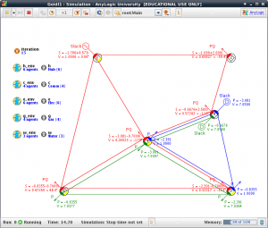
Figure 7 shows the simulation window corresponding to very simple case study, with six agents, created only for trial purposes.
Modeling infrastructure systems
Utilities are regulated and operationalized in silos but at every point in the chain—from extraction, distribution and consumption, or transformation into a service such as mobility or thermal comfort—we note that underlying technologies usually convert multiple resources (e.g., electricity and water)8.
Critical?infrastructure
So, in their most basic sense, critical infrastructure can be seen as a base for extraction, storage, transportation and transformation, from the source of resources to the services demanded by customers.
Co-evolution
Co-evolution?diagram
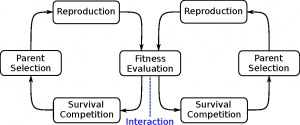
The fact that Infrastructure Systems exhibit a co-evolutionary behavior has been related by certain authors some years ago9. In the book by 10, three fundamental needs of such systems were recognized. The first was the need for the introduction of novelty, meaning a mechanism must be in place whereby variants of the original structure can be created. Second, selection pressures had to operate, such as carbon emission targets which would make some conversion points ‘fitter’ than others. Finally, a retention mechanism was required, allowing structures to be transmitted from the present to the future8. Actually the three properties
had been borrowed from Biology and are also commonly used in the field of evolutionary algorithms. Figure 9 shows a typical diagram for co-evolution between individuals of two different species.
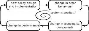
System transitions
Socio-technical systems are affected not only by physical laws but also by human behavior, regulatory agencies, government and private enterprises. In 9 the authors proposed a modelling framework for large-scale socio-technical systems (LSSTS) and defined system transitions, as a key aspect for evolution of these systems. A system transition is a “structural change in both technical and social subsystems”. Transitions emerge over time as a fundamental change of LSSTS. During transitions, the structure and the content of the physical subsystem change.
Transition?in?socio-technical?system
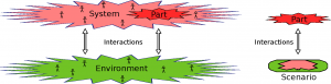
Scenarios for agent-based models
Scenario?as?a?system?part
An agent-based model is “a collection of heterogeneous, intelligent, and interacting agents, which operate and exist in an environment, which in turn is made up of agents” 11.
Because the entire environment may be an extraordinarily complicated complex system, 9 recommended the use of scenarios.
For scenario working (1) we define parts of the system that are unaffected by other parts within the system, (2) we exclude them from the system, (3) everything outside the system boundary is, therefore, exogenous, (4) every thing relevant but exogenous makes up the scenario space. 12
The evolution of the system in one simulation is not a prediction of the future of that system. One needs an impact assessment by using different system evolutions at different scenarios.
Where do we start from?
Interesting is this system representation shown in 13, p.64, for energy transitions, where technological installations is an important part.
And also the observation by 14: “A complex system that works is invariably found to have evolved from a simple system that worked. The inverse proposition also appears to be true: A complex system designed from scratch never works and cannot be made to work. You have to start over, beginning with a working simple system.”
Agent-based?model?structure
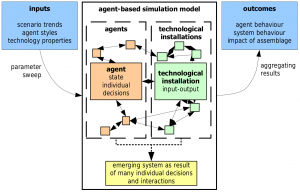
Networks of infrastructure systems
In previous sections, the special structure of a multi-carrier energy network has been analyzed, showing it is like a network of networks, and an agent based model has been developed and implemented in Anylogic. But by golly, something similar structure has been observed in infrastructure systems by 8 where the name A network of systems was used for them and some of their main elements were shown.
On the other hand, there is a fairly widespread opinion that infrastructure systems can be modeled based on agents, see for example 9 where large-scale socio-technical systems—LSSTS, are studied. But as agents live in environments and use networks to communicate which each other, then the knowledge of the networks they use may be essential to build the associated agent based models.
As evidently the set of energy networks is a subset in infrastructure networks (only a small part), a question arises: could it be possible to extend our model of energy networks in order to accommodate infrastructure networks?
A thing should be clear: in a graph only vertices and edges should appear. So if we have a model for energy networks and we like to extend the model to accommodate some more complex systems, then, the only thing we can do, is to add more vertices and edges to the model. But, of course, each of them can have a more powerful meaning.
Conversion points
Utility?Conversion?Point?(UCP)?block
Transforming utilities conversion points (TUCP)enables us to represent critical infrastructure activities, using an ensemble with four elements: extract, transform, store and deliver, being each activity can further be configured in terms of its inputs, outputs, controls, and mechanisms as Figure 13 shows 8.
There is not a right way to get quantitative realizations, like simulation models, from TUCP. The reason is that TUCP include some arrows representing qualitative ideas (i.e. the technologies arrow), that must be instanced in actual quantitative descriptions before they can be represented using conventional modelling methods, always based on numerical methods. So each actual TUCP should be realized into a quantitative description for modelling, which eventually will result into a network, mathematically represented by weighted graph.
In this way, agent based modelling can be used for case studies, using environments where agents interact which each other using these TUCP networks.
In the author’s opinion, the Transforming Utilities Conversion Points conceptualization could serve to extend the role of the previously analyzed multi-carrier energy network. This extension would be done giving the network nodes (multi-carrier energy hubs in the energy network) the role of Transforming Utilities Conversion Points (TUCP), and to assign to the network edges (multi-carrier energy conductors in the energy network) the role of utilities in infrastructure networks.
So if for energy networks we used a certain number of carriers (4 types of energy and communications in our case, as Table 1 shows), now we should add more. We think that some of the flows, somehow comparable to energy flows, could be: money flow, cars flow, flow of goods by road, product flow, water flow (clean and dirty) and any other material flow imaginable.
LSSTS?system?as?Utility?Conversion?Points?network
Figure 14 shows a entirely imaginary representation of a possible scenario in which three TUCP nodes are connected using the same lines that in the previous energy network model, that is communications (yellow), mechanical energy (black), electrical energy (red), chemical energy (green) and thermal energy (blue) and, moreover, two further non-energy carriers: cash flow (magenta) and product flow (brown).
Conclusion and outlook
In summary, the functional components of the model described in this article implement the conversion points’ ontology, in a very basic form, as an extension of existing electrical network models. And whilst the model does not go as far as the conversion points’ ontology and vision intends, it represents a step towards this vision.
A possible path forward would be through the outlined in 15 where authors argue that a complex adaptive process of models is necessary to create a Complex Adaptive System, as the so called large-scale socio-technical systems (LSSTS), complex infrastructure systems and utility conversion points, are.
In this way, the model described in this paper could be considered as belonging to this first generation of models and therefore, as a valid candidate for being the first in a process or sequence of models that after could be gradually enriched. More precisely, this first stage would be the part named physical asset by 9 and 16, where the element noted physical networks would also be made using agents. Then, the next elements in that sequence would include business management (policies, regulations), macroeconomic, psychological, and other elements of the other three indicated generations.